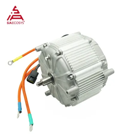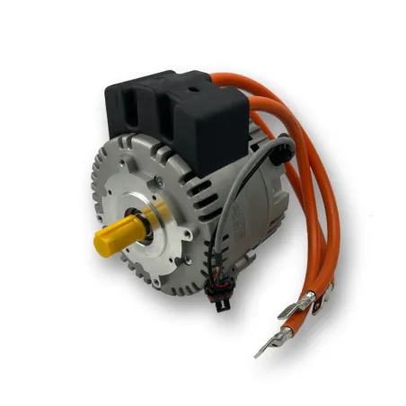
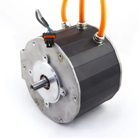
PMSM - 96V - 230A - 48KW
€11,998.80
tax. incl.
€9,999.00 tax. excl.
€9,999.00 tax. excl.
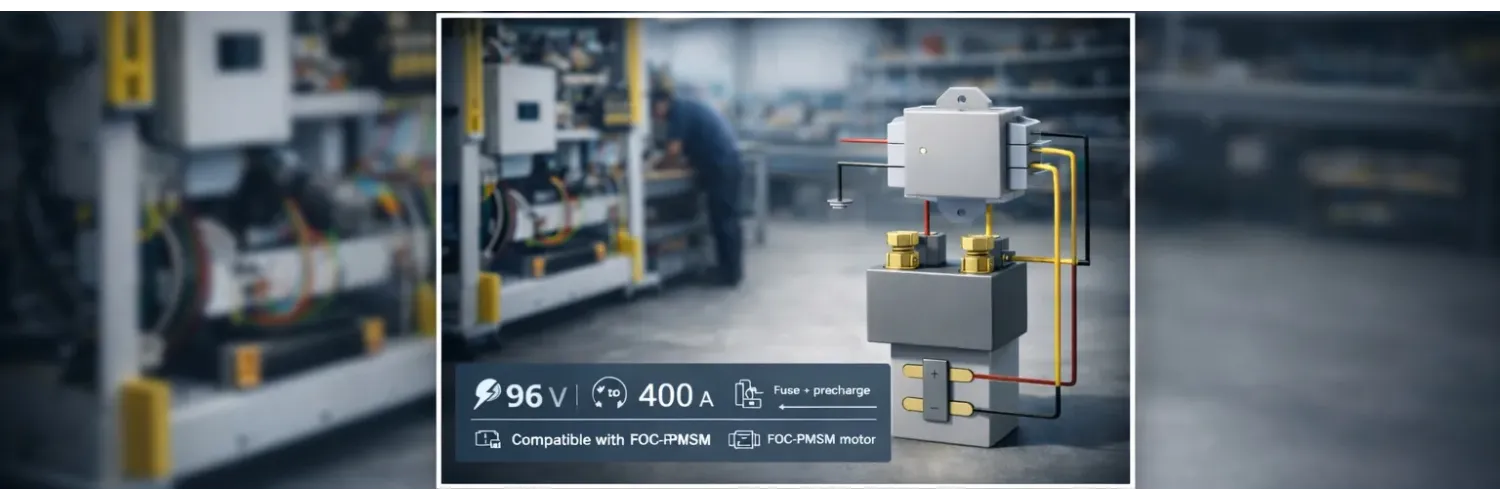
A 96 V DC architecture offers a practical voltage/current trade-off for electric traction, provided it is engineered as a system: coordinated protection devices, correctly sized precharge, vibration-robust wiring, thermal management, and a clear diagnostic strategy. This page consolidates key integration points for a 96 V DC bus built around a FOC controller and a PMSM motor (e.g., a mid-drive).
For a given power level, increasing voltage reduces current. That lowers copper losses, eases connector thermal stress, and can simplify mechanical integration, but it raises insulation and switching-control requirements on a DC bus.
On 96 V systems, available energy and the controller’s input capacitance make inrush current at power-up a primary failure mode if the sequence is not controlled.
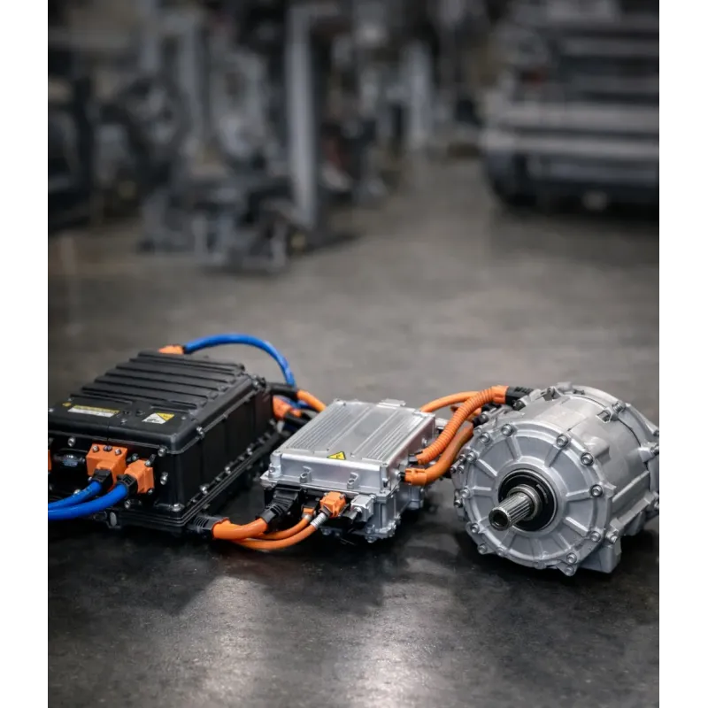
A robust architecture is built as a simple, diagnosable energy chain: short-circuit protection, main disconnection, DC-bus precharge, then controller and motor supply.
- 96 V battery (with BMS for lithium)
- Main fuse (cable protection + hard short-circuit protection)
- Main contactor (energy isolation)
- Precharge branch (resistor + precharge relay/contactor)
- DC bus to FOC controller, then motor phases to PMSM
The fuse must protect the harness and the system, not only the source. Selection must match cable ratings and DC constraints.
- Rating aligned with the allowable continuous current of cables and connectors (often the limiting element)
- Capability versus transients (acceleration peaks, control-related surges, battery dynamics)
- DC-capable technology at 96 V with interrupt rating consistent with available fault energy
- Placement close to the battery to minimize unprotected length
The main contactor must be qualified for DC voltage, realistic switching cycles, and the load nature (capacitive/inductive depending on the topology). The emergency stop is a function: safe opening command, state feedback, and associated diagnostic logic.
Precharge prevents destructive inrush when powering the controller. A traction controller typically includes DC-bus capacitors; without precharge, closing the contactor can generate very high inrush currents (limited only by ESR, cable resistance, and the contactor).
- High, repetitive inrush current that erodes electrical margins
- Contact wear: welding, sticking, accelerated aging of the contactor
- Controller faults: DC-bus instability, power-up errors, internal protection trips
The goal is to charge the DC bus to a stable level before closing the main contactor (or before bypassing the resistor). Key parameters are: Cbus, battery voltage, allowable precharge current, and the target time.
- Identify or measure Cbus (datasheet or instrumented tests) and verify repeatability versus temperature
- Set a precharge current compatible with the resistor, precharge relay, and battery capability
- Prefer sequencing based on DC-bus voltage feedback rather than a fixed timer when available
- Handle degraded cases: incomplete precharge, undervoltage, contactor fault, hot restart, limited retry logic
Sizing is not only about copper cross-section: it must cover continuous and peak current, voltage drop, losses, harness heating in bundles, and mechanical robustness in mobile environments.
Peak voltage drop must remain compatible with controller undervoltage thresholds and battery dynamics. A simple “losses + temperature rise” check on links and connectors avoids nuisance trips under load.
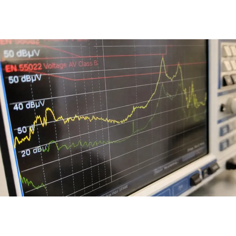
On 96 V traction systems, intermittent faults often come from routing and EMC issues (encoder, CAN, sensors). Clear power/signal separation and a coherent grounding strategy significantly reduce these risks.
- Physically separate power (DC bus, motor phases) and signals (encoder, CAN, sensors)
- Reduce current loops: keep return paths close, minimize lengths, twist pairs where relevant
- Shield sensitive signals (encoder/communication) with consistent terminations at system level
- Define a grounding strategy: avoid “accidental” return paths, control references under high di/dt
- Provide service loops and clearances to avoid bending loads on connectors
- Use connectors suited to mobile use: locking, IP rating, vibration resistance
- Qualify the harness: pull tests, thermal cycling, crimp inspection and retention checks
A robust architecture must detect, log, and support fast service return. Diagnostics should be designed alongside protection devices and control logic.
An IP67 component does not guarantee an IP67 system. Leaks typically come from interfaces (cable exits, connectors, condensation, mechanical deformation of seals).
A mid-drive IP67 motor with encoder feedback typically integrates with a 96 V FOC controller compatible with PMSM/IPM, a controlled precharge sequence, and coordinated protection (fuse, contactor, emergency stop, software limits).
The accessories below showcase a selection of components commonly integrated and/or recommended with FAQ: 96V architecture - precharge, protection and reliable wiring for electric traction to optimize installation, compatibility, and overall performance.
| Category | Accessories |
|---|---|
| BLAC MOTORS |
Integration review checklist before road testing / production ramp: focused on repeatability (pre-series) and field robustness.
| Block | Checks |
|---|---|
| DC fuse | Rating aligned with cables/connectors, DC technology, interrupt rating, close-to-battery placement |
| Contactor | DC voltage, current, cycles, safe control, state feedback for diagnostics |
| Precharge | Resistor + relay, voltage-based sequencing if possible, fault handling and limited retries |
| Wiring | Cross-section, voltage drop, heating, routing, mechanical protection, connector hot spots |
| EMC | Power/signal separation, encoder/CAN shielding, grounding strategy, loop reduction |
| Thermal | Controller temperature, harness/terminal hot spots, derating strategy |
| IP | Critical interfaces, connectors, cable passages, condensation, validation after cycling |
| Diagnostics | Fault logs, test procedures, safe shutdown criteria, event traceability |
The following topics are typically decisive to secure a 96 V architecture:
Discover below our dedicated articles, featuring detailed answers to the most common technical questions, along with in-depth information to help you better understand installation, compatibility, use, maintenance, and warranties.
| Category | FAQ / Article(s) |
|---|---|
| ELECTRIC CONVERSIONS | |
| FAQ : ELECTRIC MOTORS | |
| FAQ: VARIABLE SPEED DRIVES (LV traction controllers / inverters) | |
| FAQ: Battery Chargers |