On a lithium traction pack, the CC/CV (CCCV) charging strategy is an industrial standard: a constant-current phase to recharge quickly, then a constant-voltage phase to finish the charge without exceeding the battery’s maximum voltage. ZIVAN onboard chargers (including the SG3 range) support two distinct approaches: a standalone mode driven by an internal curve (Q9 / CU3) and a CAN-slave mode (RE) where the charging law is dictated by the BMS.
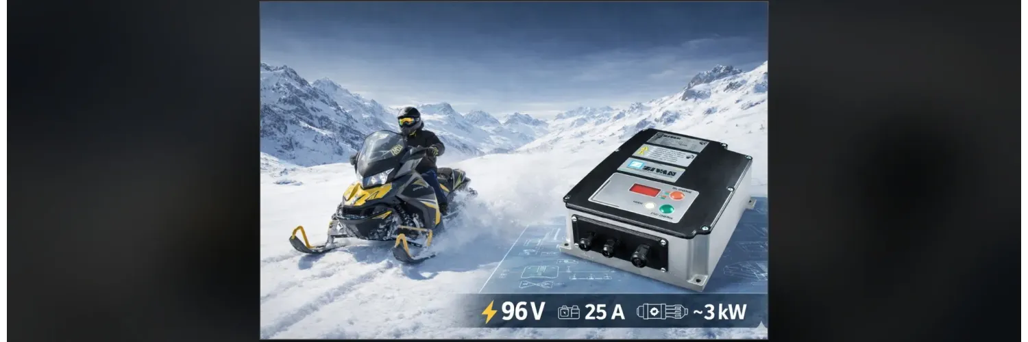
This page clarifies how CU3 works on ZIVAN chargers, the differences between Q9 vs RE, and the key integration checkpoints for a 96 V architecture (e.g., an onboard 96 V / 25 A charger – ~3 kW) in industrial and e-mobility environments.
Context
A lithium CCCV charge can be reduced to three elements: (1) a limited CC current (by the charger, the battery, or the BMS), (2) a CV voltage equal to the pack’s maximum admissible voltage, (3) an end-of-charge criterion (taper current, timer, or a BMS decision). Unlike lead-acid, prolonged equalization/float phases are generally avoided on lithium because they can be detrimental if applied incorrectly.
In real deployments (retrofit, industrial vehicles, mobile machines), the question is not only “how to charge” but also how to integrate: wiring, protections, EMC, thermal design, and consistency with the battery safety chain (contactors, enables, faults).
Q9 and RE modes
On ZIVAN chargers, two philosophies must be distinguished:
- Standard Q9 mode (standalone): the user selects a charging curve (CU1, CU2, CU3) and sets the associated parameters. The charger runs the charge autonomously.
- RE mode (CAN slave): the charger becomes a power actuator, controlled by the system over CAN (often using CANopen-like logic and configurable frames depending on the integration).
Key point: in Q9, the CAN interface may be available for monitoring (states/diagnostics) but is not used to command the charge. If CAN control frames are sent in this mode, the charger may report errors and will not follow those commands. In RE, CAN control is part of the intended operating principle.
CU3 in practice
In Q9, the CU3 curve is a standalone lithium CCCV curve. The principle is straightforward: you set a constant current (limited by the charger, e.g., 25 A on a 96 V / 25 A unit) and a constant voltage corresponding to the pack’s maximum charge voltage. The charger then manages:
- the CC phase until the target voltage is reached,
- the CV phase (voltage regulation, current taper),
- the end of charge according to its settings (taper current threshold and/or timer depending on configuration).
Before commissioning, lock down battery coherence: max pack voltage (or max cell voltage × number of series cells), admissible charge current, and end-of-charge strategy (current/time cut-off) to avoid unwanted battery-side cut-offs.
CU3 settings
| ICC (CC current) | Target current (e.g., 25 A on SG3 96 V / 25 A) | Defines the CC phase and wiring/thermal stress. Must match battery capability. |
| VCV (CV voltage) | Max pack voltage (end of charge) | Triggers CC → CV and sets the voltage ceiling. Keep below battery protection thresholds. |
| End of charge | Taper current and/or timer (config-dependent) | Stops the charge at the end of CV. Drives repeatability and battery stress. |
BMS and safety
In CU3 / Q9, the BMS does not command the charger over CAN, but it remains the battery’s safety authority: over-voltage/over-temperature monitoring, contactor management, enables, and protective cut-offs. Integration must ensure consistency between:
- the charger’s ICC and VCV settings,
- the BMS protection strategy (contactor opening, interlocks),
- system behavior on battery cut-off (contactor opening): clean stop, no erratic restarts.
Proper CU3 settings aim at a stable end-of-charge without triggering battery protection. At nominal power, a full thermal validation (long charge) is a mandatory qualification step on vehicle/machine platforms.
RE CAN mode
In RE, the charger is a CAN slave: the BMS (or supervisor) sends a current setpoint, typically at maximum at the beginning (e.g., 25 A), then reduces it as the battery approaches its limits. “Constant voltage” is not an internal CV regulation of the charger; it is achieved by progressively reducing current as decided by the BMS when a cell (or the pack) reaches the maximum admissible voltage.
Integration checkpoints:
- Watchdog and timeouts: loss of communication means setpoint to zero and a safe state.
- Clear state machine: enable/disable, faults, zero setpoint, end of charge.
- BMS-side taper control: ramp rate, thresholds, and timers to avoid oscillations and overcharge.
- Traceability: log setpoints, events, and faults for field diagnostics.
Choosing a mode
The choice between CU3 (Q9) and RE (CAN) is primarily driven by BMS capabilities, not only by ease of use:
- If the BMS cannot control a charger (no CAN, limited CAN, or no configurable frames/CANopen): CU3 in Q9 provides a standalone lithium CCCV profile with direct ICC and VCV settings.
- If the BMS can control properly: it must support robust control (frame format, strict periodicity, timing, loss-of-comms handling, state machine). In that case, RE is generally preferable for lithium: more development, but a quality and safety guarantee (dynamic limits, controlled stop, deterministic behavior on faults).
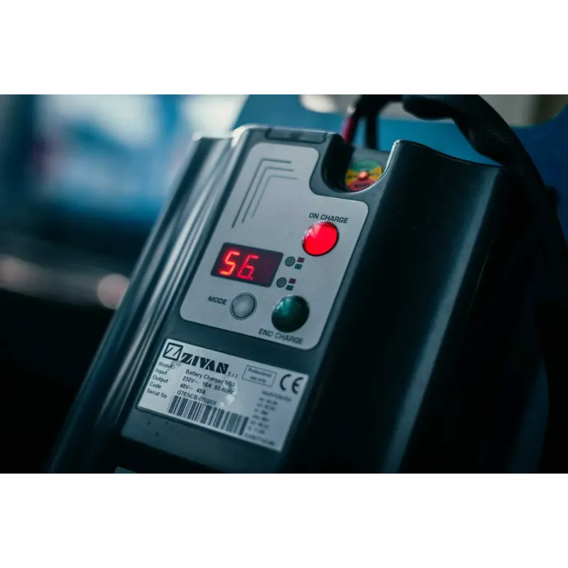
Extra benefit in RE: SG3 chargers can act as a field debug tool because the display and LEDs can be driven over CAN. This allows showing charger faults and also battery/BMS faults or other bus node diagnostics, provided the charger is powered/connected to AC (so the display is active).
Compatible accessories
The accessories below showcase a selection of components commonly integrated and/or recommended with FAQ: Lithium – using CU3 in CCCV on ZIVAN chargers (Q9 standalone vs RE CAN/BMS) to optimize installation, compatibility, and overall performance.
| Category | Accessories |
|---|---|
| BATTERY CHARGERS |
96V integration
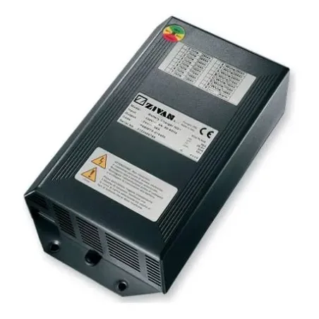
On a 96 V architecture, an IP-rated onboard charger (e.g., IP65) is an AC/DC conversion block exposed to real constraints: vibration, thermal, harness voltage drop, and EMC robustness. For a 96 V / 25 A (~3 kW) unit, the following points structure a reliable integration.
- AC input: wide-range input (typically 95–265 V~) with active PFC; provide accessible disconnect, sound earthing, and coordinated upstream protection.
- DC wiring: size cable cross-section based on length and acceptable voltage drop; at 25 A, around 6 mm² is a common baseline in onboard harnesses (adapt to harness and thermal constraints).
- Protections: coordinate with the battery chain (BMS, contactors, fuses) and consider behavior on cut-off (contactor opening, polarity issues if applicable to the system).
- Thermal: validate long charge at nominal power (charger, cables, connectors) and ensure coherent airflow; IP65 does not remove heat dissipation constraints.
- EMC / CAN: separate power and communication, minimize current loops, manage shielding and chassis reference; in RE, CAN robustness (timing, watchdog) becomes a system requirement.
In industrial e-mobility, integration quality is measured by behavior under faults (battery cut-off, CAN loss in RE, over-temperature), and by end-of-charge repeatability (no over-voltage, no oscillation, stable finish).
Logs & diagnosis
Maintenance and traceability are part of the value of an industrial onboard charger. ZIVAN architectures (depending on configuration) can provide data logging to correlate charge cycles, events and usage drift. For integrators, logging CC/CV duration, taper current, temperatures and faults improves field diagnostics, battery aging understanding and integration validation.
Applications
96 V multi-chemistry onboard chargers (lead/lithium) with an IP-rated housing and CAN connectivity are typically used in:
- Industrial electric vehicles and 96 V mobile platforms (material handling, site tractors, internal utility vehicles).
- Electric retrofit projects on machines/vehicles with 96 V packs and onboard integration constraints.
- Aerial work platforms, lifts and service equipment operating in harsh environments.
- Industrial cleaning machines with sealing and robustness requirements.
- Marine or exposed stationary applications (sealed housing, diagnostics, usage monitoring).
Articles
Discover below our dedicated articles, featuring detailed answers to the most common technical questions, along with in-depth information to help you better understand installation, compatibility, use, maintenance, and warranties.
| Category | FAQ / Article(s) |
|---|---|
| ELECTRIC CONVERSIONS | |
| FAQ : ELECTRIC CONVERSION KITS | |
| FAQ : ELECTRIC MOTORS |
Product related to FAQ: Lithium – using CU3 in CCCV on ZIVAN chargers (Q9 standalone vs RE CAN/BMS)